The mesh tool, the Create Mesh command, and the Expand command can all be used to transform an object into a mesh object. A mesh object is a single, multicolored object on which colors can flow in different directions, and transition smoothly from one point to another. By creating a fine mesh on an object and manipulating the color characteristics at each point in the mesh, you can precisely manipulate the coloring of the mesh object. You can also apply color to four mesh points at the same time by clicking the patch between them, to create broad color changes on part of the object.
About meshes
When you create a mesh object, multiple lines called mesh lines crisscross the object and provide a way to easily manipulate color transitions on the object. By moving and editing points on the mesh lines, you can change the intensity of a color shift, or change the extent of a colored area on the object.
At the intersection of two mesh lines is a special kind of anchor point called a mesh point. Mesh points appear as diamonds and have all of the same properties as anchor points but with the added capability of accepting color. You can add and delete mesh points, edit the mesh points, or change the color associated with each mesh point.

Diagram of a mesh object
A. Mesh line B. Anchor point C. Mesh patch D. Mesh point
Anchor points also appear in the mesh (differentiated by their square rather than diamond shape), and can be added, deleted, edited, and moved as with any anchor points in Illustrator. Anchor points can be placed on any mesh line; you can click an anchor point and drag its direction lines to modify it.
The area between any four mesh points is called the mesh patch. You can also change the color of the mesh patch using the same techniques as changing colors on a mesh point.
Tips for creating mesh objects
You can create a mesh object out of any path object, or any bitmap image (such as a photographic image imported from Adobe Photoshop).
There are a few important guidelines to keep in mind when creating mesh objects:
• You cannot create mesh objects from compound paths, text objects, or linked EPS files.
• Once a mesh object has been created, it cannot be converted back to a path object.
• When converting complex objects, use the Create Mesh command for the best results.
• When converting simple objects, use either the mesh tool or the Create Mesh command. However, if you want to add a highlight to a particular spot, use the mesh tool and click at the point you want the highlight to appear.
• To create a mesh object with a regular pattern of mesh points and mesh lines, use the Create Mesh command.
• When converting complex objects, Illustrator can add hidden anchor points to maintain the shape of a line. If you want to edit, add, or delete one or more of these anchor points, use the add-anchor-point tool or the delete-anchor-point tool.
• To improve performance and speed of redrawing, keep the size of mesh objects to a minimum. Complex mesh objects can greatly reduce performance. Therefore, it is better to create a few small, simple mesh objects than to create a single, complex mesh object.
Creating a mesh object
Use the mesh tool or the Create Gradient Mesh command to convert objects to mesh objects. You can also use the Expand command to convert radial or linear gradient path objects into mesh objects.
To create a mesh object with the mesh tool:
Choose the mesh tool and click a filled object. The object is converted to a mesh object with the minimum number of mesh lines.
To create a mesh object with the Create Mesh command:
1 Select a filled object.
2 Choose Object > Create Gradient Mesh.
3 Enter the number of horizontal rows of mesh lines to create on the object in the Rows text box.
4 Enter the number of vertical columns of mesh lines to create on the object in the Columns text box.
5 Select the direction of the highlight from the Appearance pop-up menu:
• To Center creates a highlight in the center of the object.
• To Edge creates a highlight on the edges of the object.
• Flat applies the object’s original color evenly across the surface, resulting in no highlight.
6 Enter a percentage of white highlight to apply to the mesh object. A value of 100% applies maximum white highlight to the object; a value of 0% applies no white highlight to the object.
Creating a mesh object using the Expand command:
1 Select an object containing a radial or linear gradient fill.
2 Choose Object > Expand.
3 Select the Gradient Mesh option in the Expand dialog box and click OK. The selected object is converted to a mesh object that takes the shape of the gradient, either circular (radial) or rectangular (linear).
Editing mesh objects
Once you have created a mesh object, you can adjust or edit its mesh points, anchor points, and mesh lines. Anchor points can be added with the add-anchor-point tool or deleted with the delete-anchor-point tool on any mesh line.
To add or delete mesh points and mesh lines:
1 Select the mesh tool .
2 Do one of the following:
• To add a mesh point colored with the current fill color, click anywhere in the mesh object. The corresponding mesh lines extend from the new mesh point to the edges of the object. Clicking on an existing mesh line adds a single intersecting mesh line.
• To add a mesh point without changing to the current fill color, press Shift and click.
• To delete a mesh point and the corresponding mesh lines, Alt-click (Windows) or Option-click (Mac OS) directly on the mesh point.
To edit a mesh point:
1 Select the mesh tool and click directly on a mesh point. Direction lines appear on the mesh point.
2 Do one of the following:
• Drag the direction points on the direction lines to edit the mesh point as you would any anchor point. For more information about editing anchor points,
• Shift-drag a direction point to move all direction lines from the mesh point at once.
• Use the direct-selection tool, the convert-selection-point tool, or the transformation tools to edit mesh points.
To move a mesh point:
1 Select the mesh tool.
2 Do one of the following:
• Click a mesh point and drag to freely move the point and the connecting mesh lines.
• Press Shift and drag the mesh point to constrain the movement to follow a mesh line. This is a convenient way to move a mesh point along a curved mesh line without distorting the mesh line.
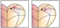 Dragging to move mesh point (left) and Shift-dragging with the mesh tool to constrain to mesh line
(right)
